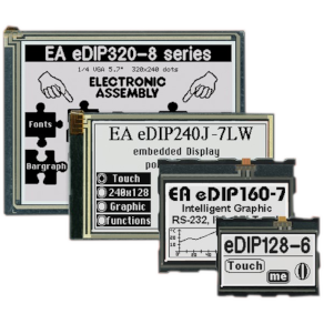
Slim, low power displays I²C, SPI, 4/8bit (3.3V and 5V)
1x8, 2x16, 3x16, 4x10, 4x16, 4x20 (Line x Char)
Low power displays with I²C, SPI (3.3V)
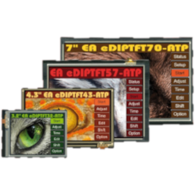
Screen size from 1.7" to 3.9"
Analogue touch-screen option
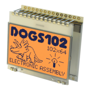
COG Text and Graphic COG Displays
SPI and I²C Interface (3.3V supply)
High contrast, True black background
High Brightness & Wide viewing Angle
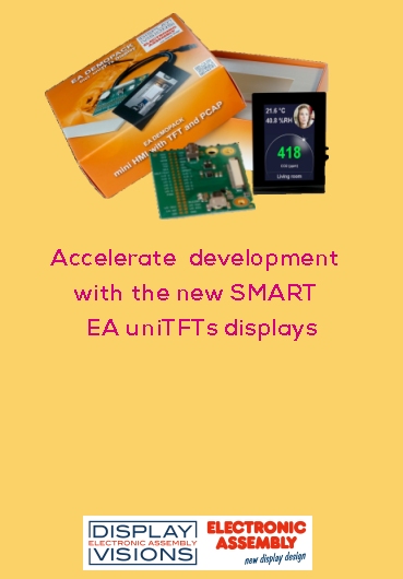
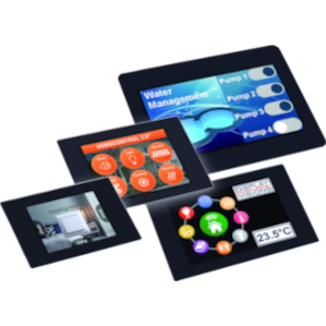
USB, SPI, I²C, Serial Interface (3.3.V)
Screen size 2.0", 2.8", 3.5", 4.3"
PCAP touch-screen
![]()
Address:
MMS Electronics Ltd
Unit 3, Whiteley Court
Pool Road, Pool in Wharfedale
Leeds LS21 1FR
United Kingdom
Mail:
sales@mmselectronics.co.uk
Phone:
Tel: + 44 (0)1943 877668